1.3. Microcontrollers#
A microcontroller (MCU) is a single integrated circuit that combines a microprocessor, memory and peripherals, which has been enabled by successive improvements in miniaturisation of integrated circuits. It is now more common to see microcontrollers used in embedded systems rather than discrete microprocessors, memory and peripheral integrated circuits because they are more convenient, compact and cost effective.
1.3.1. Hardware#
Packages#
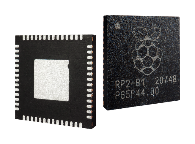
RP2040 in QFN-56 package, taken from https://www.raspberrypi.com/products/rp2040/#
Microcontrollers are packaged as either surface mount or through hole devices. These devices contain the microcontroller integrated circuit and connect it to the circuit board of the device.
Layer by layer teardown of the RP2040 package and IC, taken from <https://x.com/johndmcmaster/status/1355092011829719046>`_#
Pins#
The metal connectors on the device are called “pins”. These are assigned specific functions such as power connections, GPIO, ADC, DAC or communications. Most microcontrollers support multiple functions per pin.
Development Boards#
A development board holds a microcontroller for prototyping purposes. It allows developers and engineers to develop working devices without having to create their own special purpose circuit boards.
On development boards the pins of the microcontroller will be broken out into 0.1” (2.54mm) pitch holes, into which “headers” can be soldered.
Development boards also include convenient features like USB connectors for programming, buttons to reset the microcontroller.
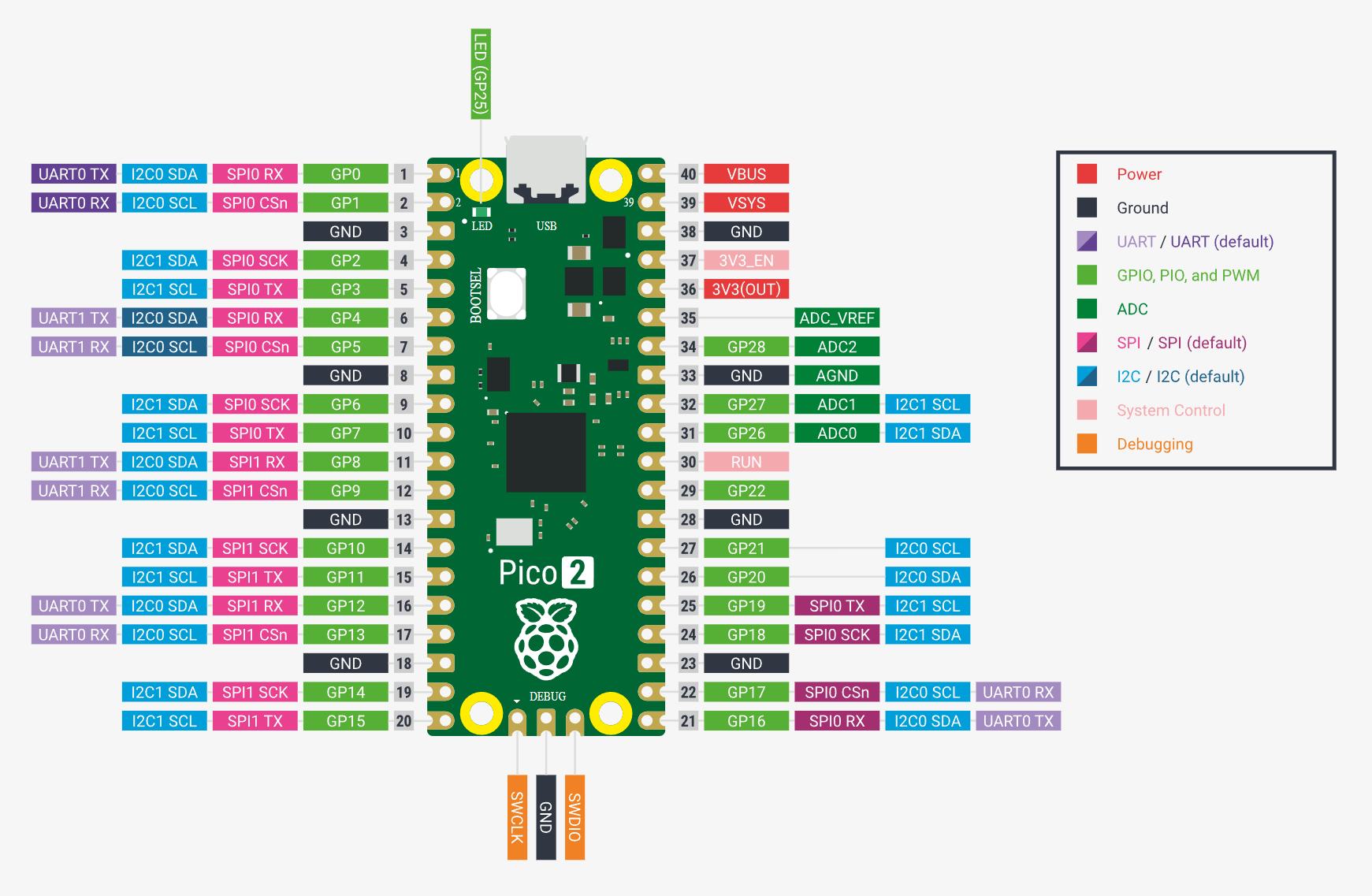
Pinout diagram of the RaspberryPi Pico 2 development board, taken from https://www.raspberrypi.com/documentation/microcontrollers/pico-series.html#
1.3.2. Software#
Instruction Sets#
An instruction set architecture (ISA) is the vocabulary a processor understands. Each model of MCU, whether an 8-bit AVR on an Arduino or the 32-bit ARM Cortex-M4 inside a micro:bit, speaks its own set of machine instructions.
The code we write in a high level language such as Python gets translated or compiled into one or more instructions from the instruction set for the processor to execute. Standarisation of instruction sets means that code that is compiled for an instruction set can be run on any MCU that uses the same instruction set. This makes it easier to developer compilers and allows flexibility in the choice of MCU since you can use any MCU with the same instruction set.
There are two main types of instruction sets
Complex-instruction set (CISC) offers a large number of highly specialised instructions which can do complex operations.
Reduced-instruction set (RISC) offers a smaller number of instructions which need to be assembled together.
Usually a CISC instruction set is implemented by having a translation layer on the processor itself that converts the complex instructions into sub-instructions. Since every extra instruction costs silicon area and power most microcontrollers use RISC style instruction sets and may not support operations that you might expect.
Examples of instruction sets used in microcontrollers:
AVRused by AVR compatible devices such as Atmel Microcontrollers commonly found in Arduino productsARM Cortex-Mused by Cortex-M compatible microcontrollers such as STM32, RP2040 and NRF series microcontrollersRISC-Vused by recent Espressif ESP32 microcontrollers
Opcodes#
Once translated or compiled, the instructions are stored in memory as a binary opcode, which is a number that the CPU’s decoder converts into real work.
As an example, consider the following translations from concept to opcode:
Concept |
Python |
Opcode bytes (hex) |
|---|---|---|
Toggle pin |
|
|
The instruction set dictates how many bytes each instruction will occupy and also how many instructions are required to complete a task, which matters on microcontrollers due to the relatively small amount of memory for storing programs and program state.
Registers#
Registers are the processor’s internal memory. Instructions operate on data stored in registers so all data must be transferred from RAM or non-volatile flash memory before it can be used.
The number of registers is usually very limited on most microcontrollers. For example on the AVR 8-bit instruction set there are 32 8-bit registers, with a subset of register able to be paired together for 16-bit instructions.
With so few registers it means that complex programs will take longer to operate as the data needs to constantly be shuffled to and from RAM onto the registers.
Peripherals and Memory-Mapped I/O#
Peripherals are accessed through “memory-mapped registers”, which are fixed memory addresses which hold data from peripheral devices such as
GPIO
ADC/DACs
Communication buses
Despite the name, these are not registers on the processor but are part of RAM. Accessing these devices through RAM is for two reasons:
it uses the same instructions/opcodes as reading any data from memory so doesn’t require additional instructions/opcodes
it is fast so there are no bottlenecks created by interacting with peripherals