2.1. Overview#
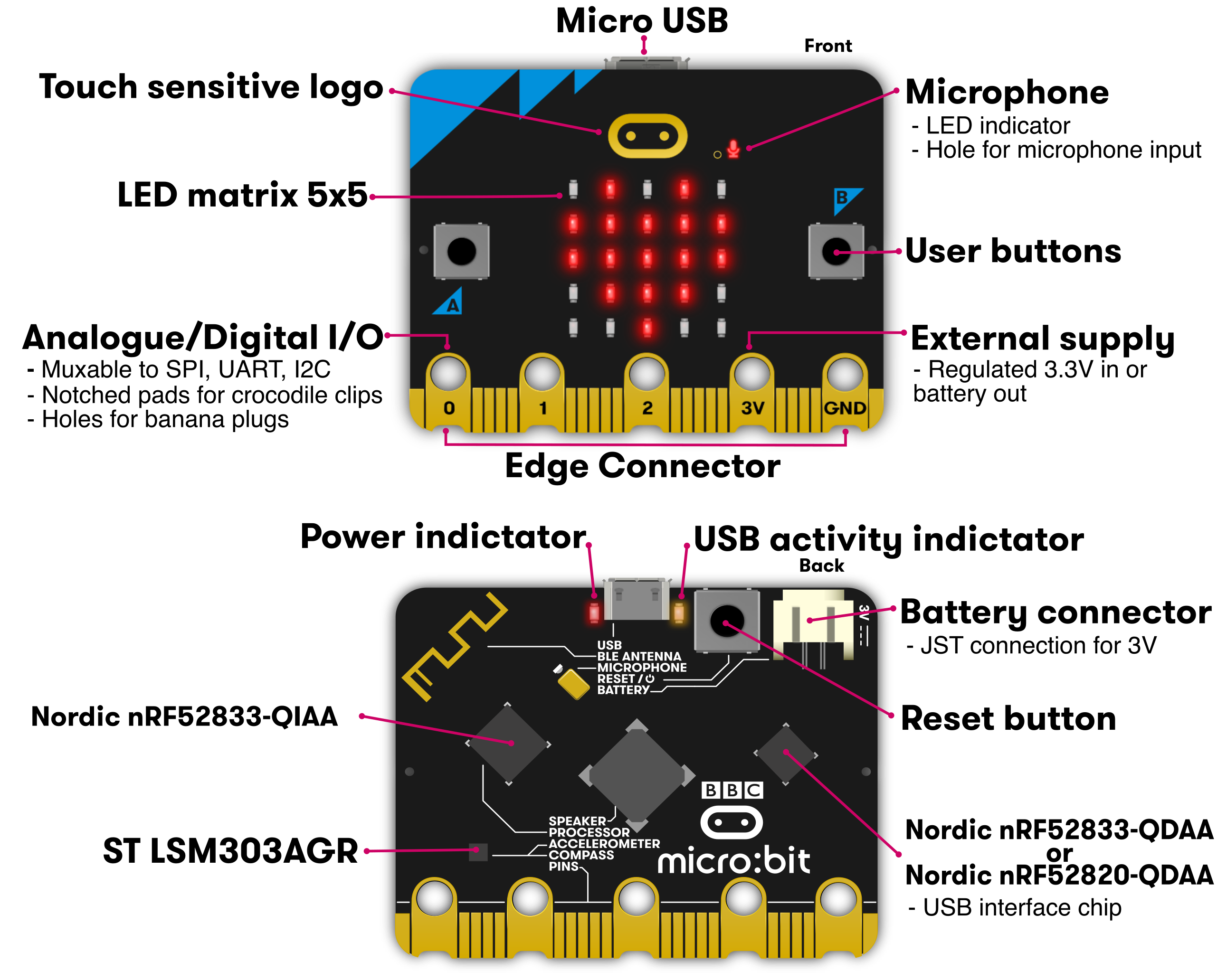
The micro:bit is a development board equipped with a relatively large number of onboard features. It comes with wireless communication, inbuilt speaker and microphone, a LED display and a pixel display.
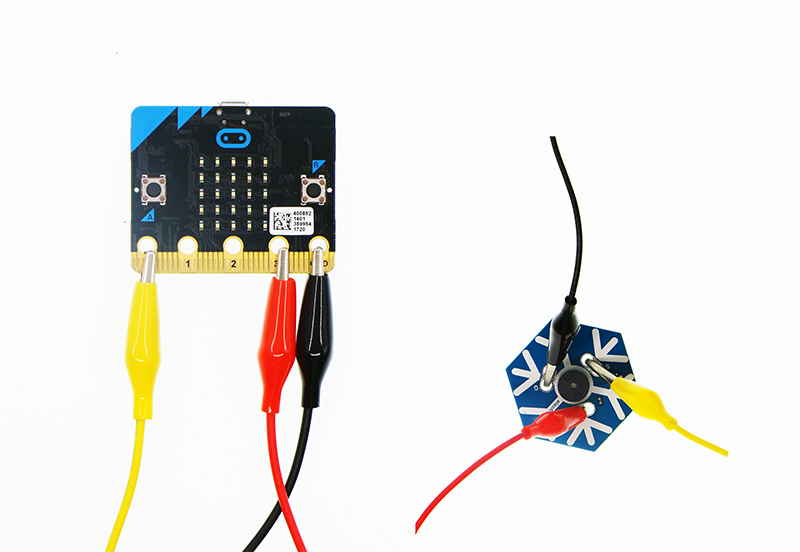
The micro:bit also has a unique edge connector, which allows for:
additional sensors or actuators to be connected via alligator clips
the board to be plugged directly into other devices with a compatible PCB connector
To program the micro:bit the officially supported options are MicroPython, JavaScript and MakeCode.
2.1.1. Diagrams#
2.1.2. Microcontroller#
The micro:bit is equipped with a Nordic nRF52833 microcontroller which includes:
Arm Cortex-M4 32 bit processor with floating point unit (FPU)
512KB of Flash Read Only Memory (ROM)
128KB of RAM
An integrated 2.4GHz radio transceiver supporting: - micro:bit radio protocol - Bluetooth 5.1 with Bluetooth Low Energy (BLE)
You may notice from the diagram above that there are actually two Nordic microcontrollers on the micro:bit. The leftmost (QIAA) is the main application processor and runs your code. The rightmost (QDAA) is responsible for USB communication only. This is an uncommon configuration that makes the micro:bit easier to program and harder to brick than a single microcontroller.
Note
Refer to Flashing for more details!
2.1.4. Display#
On the front side there is a 5x5 grid of Red LEDs, which are individually addressable with 256 levels of intensity.
2.1.5. Accelerometer and Magnetometer#
The micro:bit has a combined 3-axis accelerometer and magnetometer IC. The accelerometer measures the board’s orientation in space by sensing the direction of gravity relative to the board. The magnetometer senses the orientation of the board relative to the Earth’s magnetic field.
2.1.6. Speaker#
Sounds can be played through the onboard speaker. The speaker output pins are also connected to the edge connector for connection to external speakers or headphones.
2.1.7. Microphone#
The micro:bit is equipped with a micro-electromechanical systems (MEMS) microphone for sound input. There is also an LED indicator to show when the microphone is enabled.
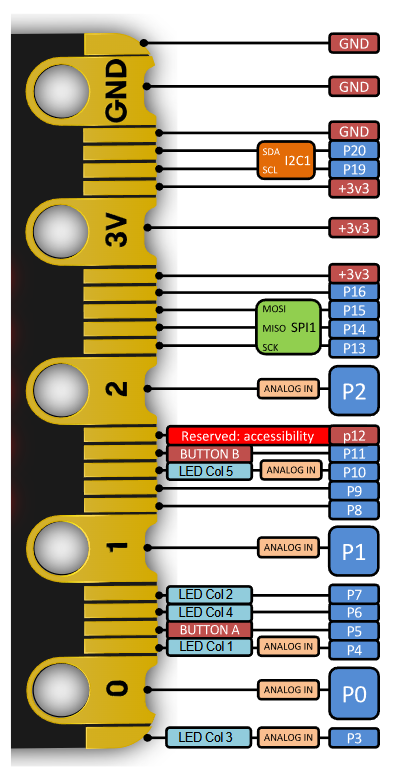
2.1.8. Edge Connector#
The edge connector breaks out the GPIO and power pins. Note that some pins serve dedicated functions.