5.10. I2C#
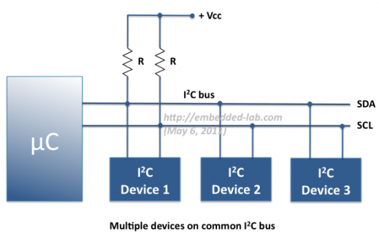
I2C (Inter-Integrated Circuit) is one of the most popular bus systems for connecting sensors to microcontrollers. It only needs two wires, SDA (data) and SCL (clock), yet it can support many devices all talking on the same bus. To use I²C effectively, it helps to understand how addressing, registers, and data transfer work.
5.10.1. Addressing#
Every device on the I2C bus has a unique address, usually 7 bits long (though some devices support 10-bit addresses). When the microcontroller (the master) wants to talk to a specific device, it begins communication by sending that device’s address on the bus.
If the device recognises its address, it responds with an ACK (acknowledge) signal, telling the master “I’m here, go ahead.”
If no device responds, the master knows nothing is connected at that address.
Manufacturers assign default addresses to each sensor type, but many modules allow a couple of address pins to be configured (for example, choosing between 0x68 or 0x69) so that more than one of the same sensor can share a bus.
5.10.2. Registers#
Most I2C sensors and chips have internal registers, which are numbered memory slots inside the device. Each register holds a piece of data, such as a sensor measurement, a configuration setting, or a status flag.
To interact with a device, the microcontroller must specify which register it wants to read from or write to. For example:
Register
0x00might hold a sensor’s ID.Register
0x01could be the temperature value.Register
0x02might be a control setting to change how the sensor behaves.
Datasheets provide a register map, telling you what each address means.
5.10.3. Data Read#
Reading data over I2C usually follows this pattern:
The master sends the device’s address with the write flag, and specifies which register address it wants to read.
Then the master re-sends the device’s address with the read flag.
The device replies by putting the requested data onto the bus, one byte at a time.
For example, reading a 16-bit temperature value might involve reading register
0x01 (high byte) and 0x02 (low byte) in sequence. The master then
combines them into the full value.
5.10.4. Data Write#
Writing data is similar, but instead of asking for information, the master provides it:
The master sends the device’s address with the write flag.
It specifies which register address it wants to write to.
It then sends the data byte(s) that should go into that register.
For example, to configure a sensor’s measurement mode, the master might write the value 0x03 into control register 0x10. The device updates its internal settings accordingly
5.10.5. Example: BME680 Sensor#
Below is a minimal example for talking to a BME680 sensor from MicroPython. It does the following in each iteration:
Trigger a sensor measurement
Waits for measurement to complete
Reads three registers containing temperature data
Combines them into an unsigned integer representation (raw ADC value)
Hint
The magic numbers such as addresses, mode numbers etc are drawn from the BME680 datasheet.
from machine import I2C, Pin
import time

# Create I2C bus on the standard pins (SCL=P19, SDA=P20 for micro:bit v1/v2)
i2c = I2C(0, scl=Pin(19), sda=Pin(20))

ADDR = 0x76  # or 0x77 depending on your module
REG_CTRL_MEAS = 0x74
REG_TEMP_MSB = 0x22

while True:
    # Trigger a single measurement:
    # osrs_t = 001 (x1 oversampling for temperature -> 0x20)
    # mode   = 01 (forced mode -> 0x01)
    i2c.writeto_mem(ADDR, REG_CTRL_MEAS, bytes([0x21]))
    time.sleep_ms(20)  # wait for measurement to complete

    # Read the 3 temperature registers
    data = i2c.readfrom_mem(ADDR, REG_TEMP_MSB, 3)
    raw = (data[0] << 12) | (data[1] << 4) | (data[2] >> 4)

    print(raw)  # Raw ADC value (not °C yet, needs Bosch compensation formula)
    time.sleep(1)